News
Problem / Challenge
Hanger pins on suspended-span bridges are difficult components to inspect reliably. FHWA-HRT-04-042, the federal highway authority document for hanger pin inspection, was written around conventional ultrasonic methods. Phased array has since become standard practice, and the question of how load state affects the inspection result was not addressed in that document. Figures 1 and 2 show how we used Salvus to mesh the structure and build a simulation of the full pin assembly and examine what a 2.25 MHz phased array inspection detects under different loading conditions.
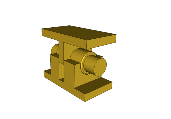
Figure 1: The simulated assembly includes the hanger pin, plates, and bearing surfaces in steel.
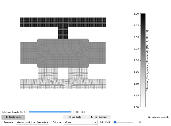
Figure 2: All contact interfaces between pin and surrounding geometry were modelled explicitly so that load-dependent changes in boundary conditions could be captured in the wave propagation simulations.
The problem with inspecting hanger pins under load is that the contact face between the pin and the bearing plate sits at the same location where fatigue cracks typically initiate. Any indication appearing there during an in-service inspection is therefore treated with concern. What the existing guidance does not address is that a portion of the ultrasonic energy from a phased array probe can travel through the pin and into the surrounding support geometry, and at high load levels the reflected signal from that path can return to the transducer at an arrival time and angle consistent with a crack at the contact face.
Solution
One way to model the load state of the pin, is by borrowing a technique from seismology called ocean loading. In its original application, ocean loading describes the deformation of the Earth's crust under the distributed pressure of tidal water masses, and the method provides a compact way to represent spatially varying pressure fields across a surface. If it were to be applied here, the same formulation can impose distributed contact pressures across the pin bearing surfaces for a set of load cases ranging from low to high, capturing how the stress state and effective boundary conditions at the contact interface change as the load increases.
To distinguish the false indication from a real crack in simulation, we used a crack module developed for Salvus that inserts crack geometries directly into the mesh. Cracks of different shapes and sizes can be placed at arbitrary locations within the model, and the module supports sharp-tipped geometries of the kind that form during fatigue, figure 3 shows the parameters that can be modified. That matters here because a rounded or slot-like defect reflects sound differently than a tight fatigue crack, and the phased array image of the two will not be identical even when they sit at the same location. By running the loaded-pin simulation with and without a crack inserted at the contact face, we can generate the echodynamic response of a genuine crack alongside the load-induced false indication and compare the two directly, as shown in figure 4.

Figure 3: Salvus crack module illustrating the formation of a sharply pointed fatigue-type crack. In simulation studies, it is vital that they accurately incorporate the specific types of defects being sought.
Figure 4: An animation showing how the simulations at high loads, where the pin is bearing hard against the plate over a wider area, a portion of the energy transmits through the interface and propagates into the clevis geometry.
Fatigue cracks in hanger pins initiate at the contact face so the location and amplitude of the false indication are similar with what a real crack would produce. An inspector following the existing FHWA procedure, which does not account for the load state at the time of inspection, has no basis in that document for distinguishing the two cases.
Conclusion
The simulations provide a visual understanding of the situation that field inspectors have observed on in-service bridges but that previous guidance did not explain. Knowing that the false indication is load-dependent and tied to energy transmission through the contact interface opens new ways to approach the problem that were not available before. What the right procedure looks like in practice, and how it should be incorporated into an update to FHWA-HRT-04-042, is something the results here would like to inform.
References
Federal Highway Administration. Guidelines for Ultrasonic Inspection of Hanger Pins. FHWA-HRT-04-042. Washington, DC: U.S. Department of Transportation, 2004.
Coreform LLC (2023). “ Coreform Cubit (version 2023.11) [computer program],” http://coreform.com (Last viewed April 1 2026).